
T: 0086 13510078491
Tianraobu Village, Hengli Town, Dongguan City, Guangdong Province, 523472, China.
Views: 0 Author: Site Editor Publish Time: 2026-09-10 Origin: Site


Upgrading or specifying a gas generator controller is a high-stakes decision. The wrong choice leads to grid synchronization failures. Poor fuel efficiency also occurs. Catastrophic downtime remains a constant threat. Modern power systems cannot afford control blind spots. Unlike diesel systems, natural gas engines require highly precise air/fuel ratio management. Spark ignition timing demands absolute accuracy. Strict emissions compliance dictates operational boundaries. These engines respond uniquely to transient loads. This guide provides an objective framework for evaluating controllers for a natural gas generator set. It strips away marketing jargon completely. We focus heavily on operational specifications. You will learn to identify integration risks. We also evaluate supplier reliability metrics. We will show you exactly how to secure grid compliance.
A gas generator's performance relies heavily on controller specifications regarding CAN bus communication, load sharing, and specialized fuel mapping.
Scalability matters: A controller suited for a 110kw silent natural gas power generator in a commercial setting requires different acoustic and telemetry features than a multi-megawatt industrial power plant.
Evaluating a gas generator controller supplier requires scrutinizing their long-term firmware support, warranty terms, and localized technical assistance.
Proprietary communication protocols can create expensive vendor lock-in; prioritize controllers with open standards like Modbus RTU/TCP.
Many operators mistakenly assume diesel hardware works universally across all power systems. The diesel versus gas divide is vast. Standard diesel controllers often fail when retrofitted to gas systems. They completely lack spark ignition control logic. They cannot manage complex gas train valves. Natural gas engines also handle transient loads very differently. A heavy block load causes a gas engine to stall if mismanaged. Diesel engines muscle through block loads using sheer torque. Gas engines require anticipatory throttle control. Success demands specialized, purpose-built architecture.
You must define what a successful implementation looks like before purchasing. Success criteria involve several strict technical benchmarks. Seamless paralleling across multiple generator units is essential. You need perfectly stable frequency during step loads. Voltage must not fluctuate beyond tight utility tolerances. Compliant emission monitoring ensures continuous legal operation. The hardware must log these metrics accurately. True success means the system operates invisibly in the background. It should synchronize to the grid without triggering reverse power alarms.
Highlighting the operational risks of substandard controllers is crucial. The cost of failure extends far beyond hardware replacement. Substandard control modules invite severe operational hazards. Engine knocking destroys cylinder heads rapidly. Improper fuel mapping causes premature mechanical wear. This forces early, expensive engine overhauls. You also risk severe non-compliance against local grid codes. Authorities issue massive penalties for non-compliance. In severe cases, utilities will forcibly disconnect your site. Evaluating the exact technical limits of your control hardware prevents these catastrophic outcomes.
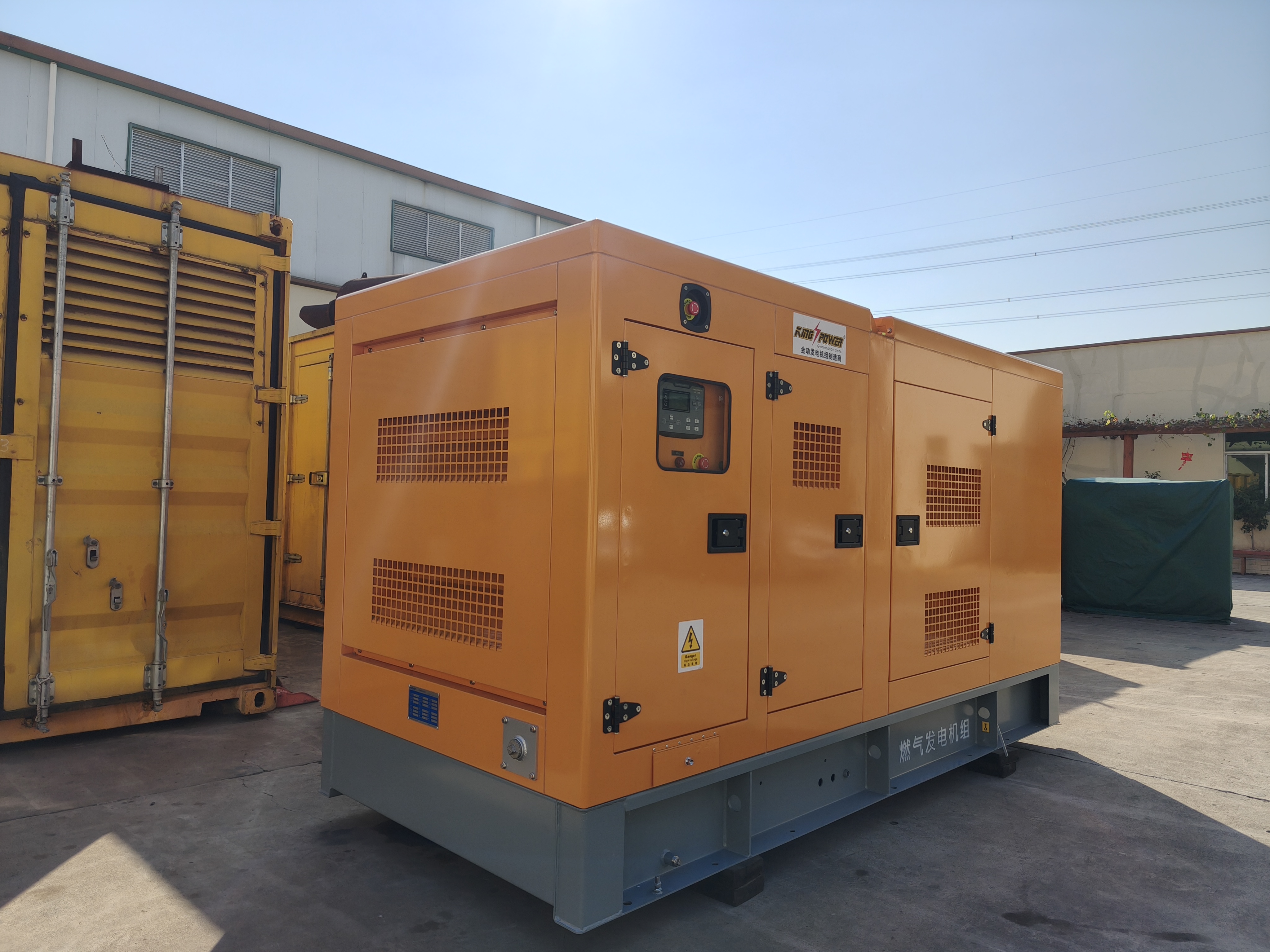
You must evaluate specific technical parameters carefully. Reviewing these gas generator controller specifications thoroughly guarantees system stability. We recommend a meticulous approach to feature verification.
Verify native support for specialized engine mapping immediately. Controllers must handle Lean-Burn versus Rich-Burn maps easily. Lean-burn engines operate under highly specific temperature constraints. The module must monitor exhaust gas temperatures across individual cylinders. Look for integrated AFR (Air/Fuel Ratio) control. Direct throttle control is equally important. These native features eliminate external third-party modules. Less hardware means fewer electrical failure points. Integrated systems respond faster to sudden load changes. They communicate directly via the internal microprocessor bus. This eliminates analog translation delays.
Assess dead-bus synchronization capabilities directly. Load-sharing precision dictates overall plant stability. You must monitor both kW (active power) and kVAr (reactive power) sharing perfectly. Evaluate operational flexibility thoroughly. The controller must manage base-load scenarios continuously. Base-load operation pushes thermal limits to the maximum. It should also handle peak-shaving operations flawlessly. Peak-shaving requires rapid startup and immediate synchronization. The hardware must transition between these modes seamlessly. Look for phase-matching algorithms offering sub-second synchronization times. Slow synchronization wastes fuel and prolongs grid vulnerability.
Modern sites demand comprehensive remote monitoring constantly. Support for Modbus RS485 and Modbus TCP is non-negotiable. Ethernet and SNMP integrations are highly recommended for enterprise visibility. Prioritize strict cybersecurity protocols always. Industrial systems face constant, evolving digital threats. Emphasize how the controller handles encrypted remote access securely. Role-based passwords prevent unauthorized parameter tampering. Read-only SCADA access protects critical engine limits. Engineers must verify firmware integrity during boot cycles. Secure remote diagnostics save thousands in unnecessary dispatch fees. Real-time data streams allow predictive maintenance scheduling.
You cannot use a one-size-fits-all approach for power generation. Application scale dictates hardware complexity entirely. Matching features to your specific environment prevents wasted budgets.
Consider a typical commercial setup. You need specific, practical tools here. Focus heavily on user-friendly HMI (Human-Machine Interface) screens. Facilities managers need intuitive, clear fault displays. Built-in acoustic enclosure temperature monitoring is vital. Small enclosures overheat rapidly during summer peak hours. Simple auto-start logic for grid failures ensures absolute reliability. The system must start without human intervention. Complex load-sharing menus confuse maintenance staff needlessly. Keep the interface focused on essential readiness indicators.
Large plants face incredibly strict utility regulations globally. Focus heavily on advanced grid protection relays. ROCOF (Rate of Change of Frequency) detection is mandatory. Vector shift detection prevents catastrophic out-of-phase reconnections. Multi-mains paralleling manages complex electrical plant topologies. You must monitor tie-breakers and mains-breakers simultaneously. Predictive maintenance algorithms maximize uptime gracefully. The hardware must log harmonic distortion metrics. It must interact seamlessly using advanced utility dispatch signals. Redundant CAN bus topologies ensure fail-safe communication.
Do not buy unnecessary software features. Multi-unit paralleling controllers complicate single-unit standby applications heavily. Extra parameters confuse service technicians easily. Over-specifying needlessly complicates commissioning schedules. Simple applications need straightforward, resilient logic. Buying a complex module for a basic task increases human error risks. Technicians might accidentally trigger parallel modes on isolated systems. Stick to hardware matching your exact operational envelope.
Application Scale Comparison Chart
Feature Category | Commercial Standby | Industrial / Grid-Tied |
|---|---|---|
Core Function | Auto-start upon grid failure | Continuous base-load and peak shaving |
Grid Protection | Basic Under/Over Voltage | ROCOF, Vector Shift, G99 Compliance |
Synchronization | Usually not required (Isolated) | Dead-bus, Multi-mains, Sub-second phase matching |
Interface Needs | Simple HMI, basic fault logs | Full SCADA integration, SNMP, encrypted access |
Complexity Risk | Low (Keep logic simple) | High (Requires specialized engineering) |
Hardware capabilities on paper differ wildly from field realities. Engineers face numerous integration hurdles daily. Understanding these traps prevents catastrophic project delays.
Integrating new controllers alongside legacy Engine Control Units (ECUs) is inherently frustrating. J1939 CAN bus mapping varies between engine brands significantly. Standard pinouts often clash during retrofits. You must trace legacy wiring schematics meticulously. Protocol translators sometimes bridge these gaps clumsily. However, translators introduce processing latency. Latency degrades throttle response times drastically. Verify native protocol compatibility before purchasing anything. Avoid relying on third-party analog-to-digital converters. Direct communication ensures the cleanest signal integrity.
PC-based configuration software saves countless hours onsite. Controllers requiring manual front-panel programming introduce massive human-error risks. Pushing buttons hundreds of times causes technician fatigue. Fatigue leads to incorrect parameter inputs. Incorrect inputs cause catastrophic engine failures. PC software allows quick template uploads. You can save configurations for disaster recovery easily. Visual logic editors simplify troubleshooting immensely. Insist on trying the configuration software before buying the hardware. Clunky software guarantees long, expensive commissioning delays.
Custom logic capabilities sound great initially. PLC (Programmable Logic Controller) functions allow unique operational sequences. However, they are only as good as the programmer writing them. Bad custom logic creates dangerous operational loops. Controllers might refuse to shut down during critical alarms. Evaluate the built-in, out-of-the-box logic first. Does it meet 90% of your operational needs? If so, avoid custom programming entirely. Rely on factory-tested logic whenever possible. Factory logic undergoes rigorous edge-case testing. Custom logic relies solely on your onsite engineer's limited testing timeframe.
Excellent hardware is useless without reliable vendor backing. Choose your partners carefully to ensure long-term success. The right supplier acts as an extension of your engineering team.
Assess their internal engineering capabilities closely. Does the supplier offer direct engineering support during commissioning? Or are they merely a box-moving sales distributor? Commissioning requires deep technical experts, not salespeople. Demand localized technical assistance. Time zone differences ruin commissioning schedules quickly. An engineer needs immediate answers while standing in front of a live panel. Ensure the supplier maintains a dedicated technical hotline. Ask for reference projects similar to your deployment scale.
Question their historical track record on product lifecycles. Component obsolescence disrupts industrial operations severely. Will they force a hardware upgrade in three years? Some vendors stop supporting current firmware prematurely. Ask for guaranteed firmware support windows in writing. A solid controller should offer a decade of reliable service. Assess their hardware backward compatibility. Can a newer module plug into the exact same wiring harness? Seamless upgrade paths indicate a mature, customer-focused manufacturing philosophy.
Trustworthy suppliers provide public access to technical documents. You should review detailed wiring diagrams before purchasing. Communication protocol manuals must be entirely transparent. Fault-code glossaries speed up troubleshooting immensely. Hidden documentation signals poor future support. If a vendor hides their Modbus registers behind a paywall, look elsewhere. Openly available software manuals demonstrate confidence in their product. We recommend downloading the manual and mapping your integration strategy before finalizing any purchase order.
Comparing controllers remains an exercise in strict risk mitigation. It ensures tight operational alignment across your entire plant. It goes far beyond merely comparing basic data sheets. You must align the hardware capabilities directly against your mechanical realities. Protect your engine using native fuel mapping and precise throttle control. Secure your utility connection using advanced grid protection relays.
We advise taking three immediate next steps. First, audit your current engine's communication protocols thoroughly. Note every sensor type and ECU requirement. Second, draft a strict requirement matrix internally. List your mandatory cybersecurity, telemetry, and paralleling needs. Finally, present this matrix before requesting any vendor quotes. Preparation prevents costly commissioning delays. Rigorous evaluation guarantees a resilient, compliant, and highly efficient power system.
A: No. Standard diesel controllers lack the necessary logic for spark ignition timing and precise air/fuel ratio management. Gas engines require anticipatory throttle control to handle transient loads. Using a diesel controller risks engine stalling, severe knocking, and catastrophic mechanical failure.
A: Grid-tied applications demand advanced grid protection relays. You must prioritize ROCOF (Rate of Change of Frequency) and Vector shift detection. Sub-second dead-bus synchronization and multi-mains paralleling are also essential for maintaining strict utility compliance.
A: No. While open-source solutions appeal to hobbyists, they lack industrial safety certifications. Industrial liability, strict insurance requirements, and grid compliance mandates require proprietary, rigorously tested controllers. Open-source platforms introduce unacceptable risks regarding cybersecurity and operational uptime.

